Compact Two-Channel Amplifier for Stereo Systems
C.G. McPROUD
Audio August 1958
A simple and easily constructed stereo amplifier with plenty of power for all but the most elaborate stereo systems. Two pair of EL84's provide a clean 15 watts in each channel.
It is fairly well established that a single-channel amplifier for a high-quality monophonic system should have upward of 20 watts for good performance without the possibility of "breaking up" on peak signals. However, when two channels are employed in a stereo system it seems quite likely that the minimum for each is somewhere around 10 watts. One of the possible drawbacks to a stereo system is the increase in space demanded for actually housing the amplifiers - to say nothing of the speakers themselves - so it was felt that an amplifier could be designed that was adequate for most users, small in size, and big in performance. The amplifier to be described seems to fulfil these requirements very well.
Tube Selection
Selection of tubes in the 10- to 20-watt range is limited - if one wishes to keep size and power requirements to a minimum. The 6V6 would be adequate from the standpoint of power output, but this tube is notoriously poor from the standpoint of distortion.
6L6's and 5881's are not too large physically for a reasonably small unit, but the current drain - in the vicinity of 60 ma per tube - demands a 250-mil transformer. Larger tubes are out of the question, and the smaller 6AQ5 is too much like the 6V6 to warrant much consideration. This leaves only the EL84 - but this is a very good solution, for two of these tubes with 300-volt power supply are easily capable of 15-watt output. The 6360 - a dual tetrode - is capable of putting out 10 watts, but the screens are common so the efficiency and low distortion of the Ultra-Linear circuit may not be used. Consequently, the EL84 - a European tube available from aither Amperex or Mullard - was selected.
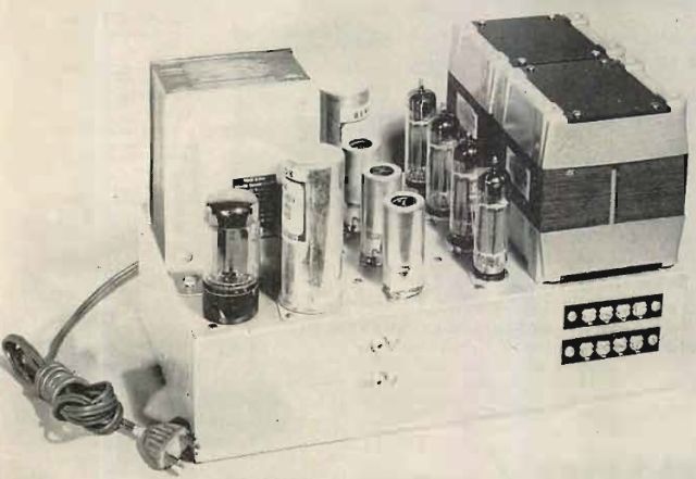
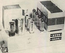
Fig. 1. Combining two 15-watt amplifiers onto one chassis results in a stereo "package" which compares favorably with most any amplifier available.
For the amplifier circuit, the Philips Technical Library book, 'Valves for A.F. Amplifiers" was consulted, and a good start was founf in the article "High-Fidelity Amplifiers with Two Tubes EL84 in Push-Pull". This circuit employs an EL86 as a pentode first stage, followed by an ECC83 (12AX7) as a "long-tailed pair" phase splitter, and the EL84's in push-pull. To reduce the gain to a more practical value for a basic amplifier, as well as to reduce the total number of tubes, the EF86 pentode was replaced by one half of an ECC83, and the remainder of the circuit followed fairly closely. With this arrangement, the first stage of each of the two channels employs half of one double triode, so that one "tube" serves both channels. From that point on, both channels are completely separate, except for the common power supply.
The phase-splitting stage is cathode coupled, with the input signal being fed direct to one grid at the same d.c. potential as the plate of the first stage, and with a decoupling resistor to the second grid which is bypassed for a.c. to ground, yet maintained at the same d.c. potential as the signal grid. The plate currents for both sections of the tube flow through a large cathode resistor, and since one grid is maintained at an a.c. ground potential while a signal is introduced to the other grid, plate current variation across this resistor provides an effective drive to the second section. The circuit has low distortion, and when carefully constructed so that the capacitances of the two plate circuits are kept to low and practically equal values, the over-all balance is excelent. To ensure good balance in practice, the plate-load resistors must not be exactly equal - the Philips book recommends balancing to approximately 5 per cent by selecting from 10-per cent resistors, with the larger of the two being used as R9 in the schematic, Fig. 2.
For proper operation with tha plate voltage selected, the grids of the phase splitter should be maintained at a d.c. voltage of approximately +90, and by selection of a plate-load resistor value for the first triode, togethervwith bias resistor, the voltage drop across the former may be made to provide this value. The direct coupling between these two tubes results in a zero phase shift at low frequencies and contributes to its stability.
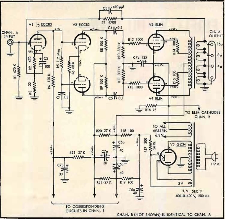
Fig. 2. Schematic of the two-channel amplifier. The "B" channel is not shown, but is identical with the "A" channel, and one ower supply serves for both.
Output Transformer
Quality in any amplifier is very largely dependent on the output transformer, and while there are many smaller transformers than the ones selected that wouls permit the construction of a smaller unit, it is believed that there is no substitute for plenty of iron and copper, and since quality was the first consideration and over-all size of the amplifier was second, the new Partridge P-5000 series was chosen. With 10 db of feedback, these transformers are rated at 20 watts at 30 cps for less than 1 per cent distortion, or 35 watts at 50 cps. Since the tubes are capable of only about 15 watts, this was considered more than adequate to ensure good performance. Leakage inductance from primary to secondary is specified as 5 mh, which is the same as from one-half of the primary to the other. Shunt inductance of the primary is high, and rated at 450 H at a 4-watt output at 50 cps. Thus good low-frequency performance could be expected. The units are constructed with cast aluminium frames, and are very rugged in appearance, as may be seen in Fig. 1. The secondaries are wound in four separate sections, permitting the use of series connection for a total of 16 ohms output, combinations of series and parallel connections for 4 and 8 ohms, and all four windings in parallel the output impedance of 1 ohm.
Common Power Supply
Since both channels are putting out essentially the same signal - a less severe requirement than would be encountered if both had entirely separate signals - a common power supply is indicated. The power transformer selected for the job has somewhat higher secondary voltage than necessary, but this permits a high value of current-limiting resistor between the rectifier tube and the first filter capacitor, reducing peak current drain through the rectifier and contributing to cool operation of the transformer. Separate filtering is provided for the two preceding stages. Since both halves of the amplifier work at identical voltages, performance of the two channels is very nearly identical also.
One of the principal objects of this design was to provide the utmost in reliability so that one could build the amplifier, put it in service, and forget it entirely. So far it has proved to have this degree of reliability, and it runs cool, with all components well within their ratings.
Construction
The layout is fairly obvious from Fig. 1. The four EL84's are seen next to the transformers, while the three ECC83's are in the shielded sockets. So as to provide identical physical layout for the phase splitter and output stages of the two channels, the first and third tubes and the phase splitters, while the center ECC83 is used for the two first stages. All the heaters are biased positively by the amount of bias on the output stages - approximately 12,5 volts - by the simple expedient of connecting the center tap of the 6,3-volt winding to the cathodes directly. All chassis connections are made at the input jacks to avoid any possibility of ground loops, and each grounded circuit is run to these jacks separately. R17 is connected directly from the cathode of the GZ34 rectifier to the first filter capacitor section, and R18 and R19 are connected directly across the capacitor. The junction of R20, R21, and R22 in a tie point, from which R8 and R9 go to V2 plates. A wire leads from this tie point to a second one adjacent to the second-channel phase splitter to accomodate the plate resistors for this stage. A third tie point adjacent to V1 serves to connect R4 and its B-channel equivalent to the first stages. R2, R3, R7, C2, and C3 are mounted on four double tie points located between the two transformers under the chassis.
Since it was expected that the amplifier would be switched on and off from a control unit, no switch was provided on its chassis. No balance controls are needed for this circuit, and R8 and R9 were selected to a 5-per cent difference. The amplifier does not seem to be at all critical in construction, and no trouble was encountered in operation from the moment it was first turned on.
The values shown in the feedback circuit, R7 and C3, are for use with the 16-ohm output connection. For other output impedances, divide the resistor value by (16/Z)½, where Z is the new output impedance, and multiply the capacitor value by the same figure. Thus for the transformer soecified, the resistir values should be 3600, 2400, and 1200 ohms, respectively, for output impedances of 8, 4, and 2 ohms. Capacitor values should be 620, 910, and 1800 µµF respectively, for the same impedances. It would be better, however, to actually choose the capacitor value by the use of a square wave and a 'scope, if these instruments are available.
Performance
Using the 2-per cent IM distortion point for rating the amplifier, this unit would be called a 17-watt amplifier. Harmonic distortion is well under 0,5 per cent at this point, and both sides of a sine wave begin to break up symmetrically at the 17 watts.
Frequency response is within 1 db from 17 cps to 85 kc, with the power output dropping 3 db at 12 and 64,000 cps. Adjustment of feedback for an optimum square wave at 10 kc reduced the very-high-frequency output slightly - with a capacitor at Cs the half-power point was raised to over 90 kc, but in the interest of better square-wave response and greater stability the given value of Cs was chosen.
The amplifier reaches its rated output at an input signal of 0,1 volts. This is relatively sensitive, and a voltage divider at the input would serve to decrease the sensitivity so that a 1-volt input, for example, would drive the amplifier to its normal maximum output. However, since stereo pickups have lower outputs than the monophonic counterparts, the additional sensitivity may be needed.
In listening quality the amplifier compares favorably - within its power capability - with several larger and more elaborate units. And in a small or average listening room, don't ever doubt that 15 watts can be loud. It might not be nearly enough for the auditorium, but few of us have listening rooms comparable to Carnegie Hall in size. Two 15-watt channels put out as much power as one 30-watt amplifier, and practically anyone will admit that 30 watts is nearly always adequate.
PART LIST
(Two each are required for all designated parts except those which are common to both channels. These are preceded in the list by asterisks.)
C1 .05 µf, 400 v., paper
C2 100 µf, 3-volt, electrolytic
C3 470 µµf, 500 v., mica
C4, C5 0.1 µf, 600 v., paper
*C6a,b,c 40-40-40/450, electrolytic
*C7a,b,c 30-30/450, 125/27, electrolytic
R1 470 K, ½ watt
R2 470, ½ watt
R3 22, ½ watt
R4 120 K, 1 watt
R5 1.2 meg, ½ watt
R6 68 K, 1 watt
R7 4700, ½ watt
R8, R9 100 K, 1 watt
R10, R11 330 K, ½ watt
R12, R13 1000, ½ watt
R14, R15 100, 1 watt
*R16 75, 10 watts
*R17 300, 20 watts
*R18, R19 100, 5 watts, wirewound
*R20, R21, R22 27 K, 1 watt
T1 Partridge P5201, plate-to-plate load 9000 to 12,000 ohms; secondary, four equal 1-ohm windings.
*T2 Power transformer: 400-0-400 v. at 200 ma; 6.3 v. CT at 5 a; 5 v at 3 a. Triad R21 or equivalent
Miscellaneous
1 7x12x3 chassis, aluminium
4 Noval sockets
3 Noval sockets with shields
1 Octal socket
2 Phono jacks
2 4-terminal strips
1 Power cord
1 Grommet for power cord
4 EL84's; 2 ECC83's; 1 GZ34.
Assorted tie points, hardware, etc.
")
")
")
")
")