More About Hum
HAROLD REED
Audio January, 1957
After all of the obvious and usual means have been tried in an effort to eliminate a particularly troublesome case of hum, it may sometimes be found to be due to an unusual cause such as this.
MUCH HAS BEEN WRITTEN about hum in audio amplifiers. The author has somethimes thought, in some of his writings, that he had covered the subject quite thoroughly, onle later to be encountered by hum conditions in circuitry not presented before by the writer, nor found discussed in other articles. One such condition will be considered in this article.
It is well known to audio amplifier constructors, that the input tube operating with low signal levels - such as the first tube in a preamplifier - should have minimum heater heater to cathode leakage. This leakage is due to a current flow between heater and cathode, which elements are separeted by a special type of insulation.
There are numerous ways to ease or eliminate objectionable hum in the amplifier output due to this leakage. As they have been well covered in technical publications, they will not be enumerated here. One of the most effective, of course, is to place the cathode as near to ground potential as possible. A large cathode bypass capacitor is normally used for this purpose.
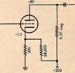
A 20-µf capacitor at the power line frequency of 60 cps has a reactance of about 130 ohms. Figure 1 shows a common circuit of a triode with the 20-µf capacitor placing the cathode 130 ohms above ground and the 3900 ohm resistor providing a d.c. bias on the tube of 1.2 volts.
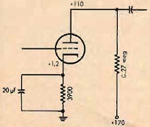
Fig. 1. Typical schematic of input staged of a high-gain amplifier with cathode resistor bypassed in the customary fashion.
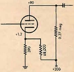
Fig. 2. Method of reducing cathode-to-ground impedance without the use of a bypass capacitor.
For a number of years the author has been working with circuits which place the cathode near ground potential without the use of a bypass capacitor. This circuit is not familiar to most audio workers but recdently it is being more widely employed. The arrangement is given in Fig. 2. Here it will be seen that the cathode is placed only 390 ohms above ground. To maintain the proper d.c. bias a 68,000-ohm resistor is connected from the cathode to the plte supply. The circuit works and has been used many times. Because the experimenter will be seeing this circuit more often, and using it, the author brings to attention one case when conditions were not as expected and hum presented quite a problem.
The circuit of Fig. 2 was used in a preamplifier circuit as had been done many times before. This time, however, hum level was extremely high when the a.c. power plug was was connected to the power line one certain way, dropping to a reasonable value when the plug was "turned over". One unit displayed a 17-db variation in hum output. With most amplifiers there is a "best" way, from the standpoint of hum, to insert the a.c. plug, but rarely with a resultant variation as great as 17 db.
The Cure
Many things were tried to eliminate the difficulty. It was definitely proved that the hum entered the grid of the input stage of the amplifier. All input lead were removed from the grid of this input stage and a 0,47-meg resistor placed from the grid to ground. All a.c. wiring except filament leads was at least 10 inches from the input tube. Filaments were then supplied from a 6-volt battery which reduced the hum variation by only 5 db. This then, was not a simple matter of heater-cathode leakage at the a.c. power frequency. Nothing helped except balancing out the hum with a hum bucking potentiometer in the filament circuit adjusted for each position of the power plug. Since the amplifier was to be used in portable record players, this remedy did not provide a practical solution but could have been used for a permanently installed amplifier even though it is not the workmanlike solution.
It was then found that balance of the a.c. hum output with changing of the plug could be obtained with the common circuit of Fig. 1. The amplifier was build on a steel chassis instead of aluminium as had been used for prior units, so naturally, a.c. fields were given special consideration. Originally, the 115-volt a.c. supply wiring was arranged as illustrated at (A) in Fig. 3. It can be seen that the supply leads, power transformer leads, and turntable motor leads were twisted together only for a portion of their total lenght. In Fig. 3, (B) shows a revised method of running all 115-volt a.c. leads, whereby each pair is twisted together continuously up to the point of connection. This method of dressing the a.c. leads did the trick and the circuit of either Figs. 1 or 2 could be used with equal results. With either circuit the variation in hum level when "turning over" the a.c. power plug amounted to no more than 2 db and the hum was sufficiently low.
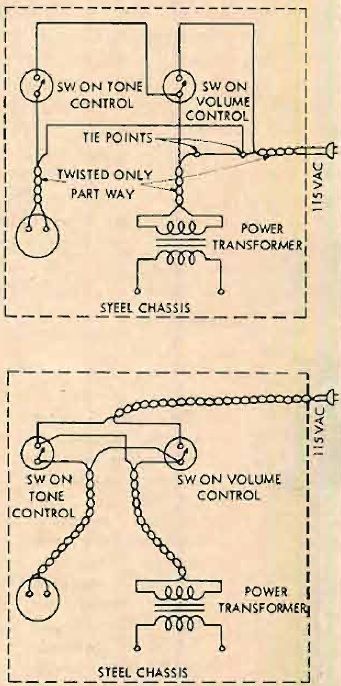
Fig. 3. (A) shows the original wiring of a typical tape recorder with the a.c. line not being twisted throughout. (B) shows rearrangement which eliminated a tricky case of hum.
The writer has arrived at a conclusion concerning the undesireble condition but is not entirely satisfied with it. The reader may have some ideas concerning this problem and his suggestions will be welcomed.
")
")
")
")
")