A Quality Dynamic Headphone Tube Amplifier
by Helmut Becker and Michael Oberesch
Glass Audio 01-0-1988
Only a few of us are privileged to listen to music at a volume comparable to the original performance. It's not because we lack appropriate equipment, but rather the neighbors force us to reduce the volume. There are two answers to this problem. We can either move to an apartment far away from civilization, or we can use headphones. The second option is definitely less expensive and offers an additional advantage: for quality sound, no loudspeaker can compete with headphones.
Most stereo manufacturers seem to ignore the fact that headphones are among the best transducers. Nearly all amplifiers have a headphone jack, but this output is often inadequate at best.
Plain, Bad, Simple
Usually, headphones are connected in parallel with the loudspeakers, where, as an option, the loudspeakers may be switched off. Headphone systems are available with impedance from 8 to 2kΩ, but usually a resistor with approximately 300Ω is connected in series with the headphones.
This prevents overloading from too high a voltage at the 8Ω loudspeaker output. When connected to high impedance systems, this resistor causes only a negligible voltage drop.
Up to this point, everything seems fine. The resistor solution, however, ignores the fact that dynamic headphones, as well as loudspeakers, need to be damped through the amplifier's low internal impedance. The above mentioned series resistor systematically prevents such damping.
An additional grawback is the relatively low voltage supply used in power amplifiers. High-quality headphones are almost exclusively high impedance (600-2kΩ) and require a correcponding high drive voltage. The output stages designed for low impedance loudspeakers cannot fulfill this requirement.
Therefore, the only solution is a special headphone amplifier. A power amplifier dedicated to driving loudspeakers has a low internal impedance and drives a very low impedance load with a relatively small voltage swing and a high current. A transistor can handle this task perfectly, but can the amp also drive a relatively high impedance load with a high voltage swing and low current? Of cource, by using transistors, we can design an appropriate circuit that will do the job. There is, however, another component some of us fondly remember: the tube.
The Ideal Circuit
For the above-mentioned requirements, a tube circuits is ideal. High supply voltage is a condition for tube operation, so it can easily support high voltage swings. Because the load is high impedance, you do not need an output transformer such as is required to drive a loudspeaker. This results in a high quality, transformerless tube output stage that is superior to most transistor amplifiers.

FIGURE 1: The basic circuit diagram.
Of course, you don't want to ban all semiconductors. In areas where tubes have their weak points (they are subject to certain manufacturing tolerances, and they show, as thermally heavily-loaded coponents, a relatively high aging rate), use semiconductors to control and stabilize operating condition variations.
When you connect headphones to the output of an otherwise excellent loudspeaker amplifier, you often hear something other than music. The connection produces noise, hum, crackles and hisses; the loudspeaker doesn't reproduce anything like this. Headphones are, by nature, more sensitive trnsducers than loudspeakers. They even produce very low noise and hum voltages. The requirements for a headphone amplifier are, therefore, very demanding.
Excellent Sound
The circuit in Fig. 2, designed by Helmut Becker and for which a patent is pending (P3200 517,2), displays excellent behavior. When compared to the significantly more expensive Onkyo P3090, no essential differences were detected. When connected to the DT880 Beyer Studio dynamic headphones, the Becker amp clearly and naturally reproduced the dynamic passages flawlessly; the voicess and orchestra were presented without coloration.
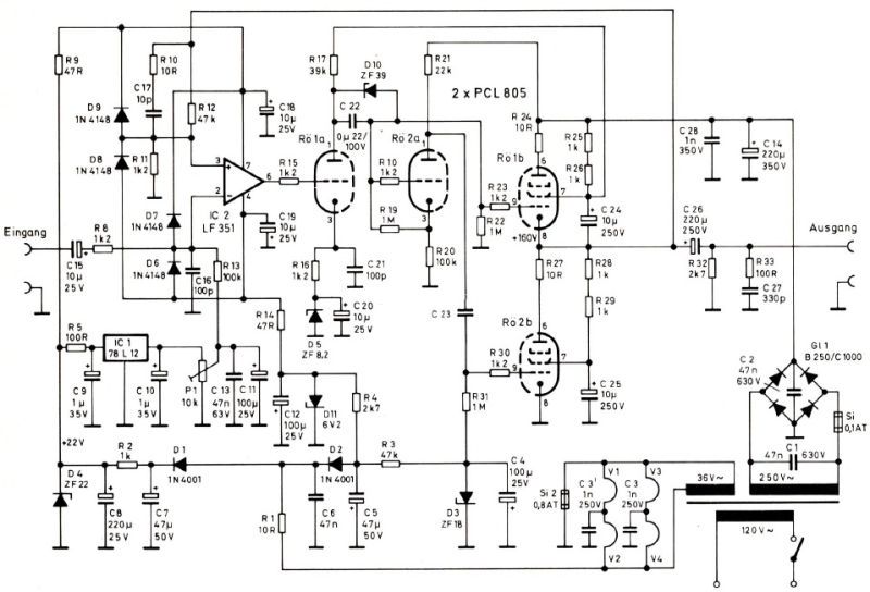
FIGURE 2: The complete headphone amp circuit diagram.
The advantages of this circuit include:
- excellent measurements results (see Table 1);
- well-balanced, powerful, clear sound;
- good dynamic range, therefore suitable for CD;
- high damping factor and low internal impedance;
- transformerless matching to impedances between 30 and 3kΩ;
- expandable with preamplifier to a full-range, linear amp.
The Circuit
As shown in the basic circuit diagram (Fig. 1) the two output tubes are connected in series for DC voltage so that the available supply voltage is shared by both tubes.
To avoid unnecessary high supply voltage, you must use tubes that can work with high current at an anode voltage of approximately 150V. Since the product family of audio-frequency tubes is geared toward high anode voltages, try using the triode-pentode PCL805 that was used ten years ago as a standard part in TV sets.
The PCL805 meets the above-described requirements, but shows, in other respects, serious disadvantages which you must consider and eliminate when designing this circuit. For example, you must use a control circuit to suppress the relatively strong hum generated by the filament current. In addition, you must compensate for the highly nonlinear grid characteristics.
Figure 1 shows the basic circuit diagram, which consists of three functional groups:
- reference voltage source for all reference points;
- operational amplifier as a control element;
- tube output stage.
Tube Output Stage
Tube 2 and 3 are connected in series for DC voltage and, therefore, the same current will flow through both. Adjusting the voltage drop to the same value across both tubes will result in maximum output swing capability.
Tube 1b is used in a grounded-anode circuit, whereas tube 2b is connected in a grounded-cathode circuit. The negative bias on the grid of tube 2b adjusts the quiescent current of the output stage. For Class AB operation, you shoul choose the quiescent current.
Tubes 1a and 2a simultaneously serve as driver stages and take care of the out-of-phase grid drive voltages for the output tubes. If the grid voltage at tube 2b increases, the grid voltage level at tube 1b must also increase, and vice versa. This cause the voltage level at the connection point A, between tubes 1b and 2b, to shift accordingly. The entire circuit works as an electronic potentiometer connected between ground and supply voltage. Its output is connected to the output capacitor C2.
The Operational Amplifier
The tasks of the operational amplifier are to control the operating conditions of the DC-connected amplifiers, and to control the audio-frequency signal.
A DC coupling is necessary to control operating conditions of all amplifier stages from one circuit location. As shown in Fig. 1, this is true for tubes 1a, 2a, and 1b. The quiescent current of tube 2b is fixed only by the negative-bias voltage. This determines the internal resistance of tube 2b. The voltage level at point A is divided by the ratio R1 and R2, and the resulting op amp voltage compares with the reference voltage URef. The output voltage of the op amp will shift the operating point of tubes 1a and 1b until the voltages at the inverted and noninverted op amp inputs are the same. The reference voltage URef, applied to the inverting input of the op amp, also defines the voltage level at point A. If URef is chosen so that the voltage level at point A is equal to half of the supply voltage Ua, both output tubes will have the same internal resistance and consume the same power. Furthermore, the output swing capability will reach its maximum.
Figure 1 also shows the audio input signal superimposed on the reference voltage. The quiescent currents modulate at the input voltage frequency so that the output signal of the amplifier becomes a direct copy of the input signal. It is, however, amplified according to the ratio of resistor R1 and R2.
This rather complicated control circuit features some remarkable characteristics. One problem of tube circuits is the hum caused by the filament current. The AC current flowing through the filament results in a magneic field, which also reaches the cathode and leads to a 60Hz modulation of the anode current. If such a hum arises within the loop of this circuit, controlled by the op amp, it will be completely eliminated if the reference voltage is clean and hum-free. You can easily fulfill this condition by using a fixed voltage regulator to carefully filter and smooth the reference voltage. You will be able to achieve a signal-to-noise ratio of 130dB(A).
A further advantage of this design is the complete compensation of the nonlinearities of the tube's characteristics. Manufecturing tolerances and changes due to aging will also be compensated for automatcally. Furthermore, the control circuit reoresents a strong negative AC feedback, which results in an extremely low output impedance.
Power Supply
Although the amplifier, with its hybrid circuitry, needs numerous supply voltages, the power transformer can operate with only two secondary windings. A winding with 250V and 100mA load current is significant to generate the anode voltage necessary to supply a stereo output stage. The second winding generates the filament voltage for the tubes. The PCL805 requires 18V at 300mA filament current. Since the two tubes will be connected in series, you must choose a transformer voltage of 36V with 0.7A current capability. The positive and negative supply voltage for op amp, as well as the negative bias voltage for tube 2b and the positive reference voltage URef, are derived from this winding.
Construction
Unfortunately, it was not possible to avoid a double-sided printed circuit board when we constructed this circuit. For this reason, only experienced do-it-yourselfers should try etching this board.
As for the stuffing, start with the power supply. You must install the following components: rectifier G11, diodes and Z-diodes D1-4 and D11, capacitors C1-14, resistors R1-5, trimpot P1, fixed voltage regulator IC1, and the two fuses Si1 and Si2.
Before you connect the transformer to check the voltages, a word of warning concerning high voltage: the anode voltage of the amlifier is more than 300V. This voltage level is high enough to send you to the "happy hunting grounds". If it is absolutely unavoidable, only work on the amplifier with the power switched off, and then only with the greatest of care. Even after you switch the supply off, the voltages on the high-voltage electrolytics (C14, 24, 24', 25', 26 and 26') remain high for a long time. Before you start working on the wtitched-off amplifier, discharge the above-mentioned capacitors. For discharging, use 1k/4W resistor. Never short the caps, because electrolytics can be destroyed due to the short surrent peaks of more than 10A.
Now, swich the amplifier on and check the voltages against ground:
C14 approx. +315V
C4 -18V
C8 +22V
C10 +12V
C12 +6V
Adjust the voltage level on C13 to approximately 3.5V by the trimpot P1. If all voltage levels are correct, you can solder the tube sockets and install the tubes, but only after you have switched off the amp and discharged the caps. Now, check to see if the filaments are functioning by switching on the amp again and wainting a few seconds. You shouls see a glow of the filaments inside the tube.
After switching off and discharging the system once again, you can continue the stuffing. If all components are soldered, switch the amp on and adjust it by measuring the voltage levels on C26 or C26'. The voltage should be in the range of 100 to 250V, and must be set to approximatelly 160V with P1. Then, short the input and check the channel one output on an oscilloscope. Nothing should be present at the output except a very low noise signl. Check channel two for the same.
To adjust the symmetry of your amplifier, apply a 1kHz signal to the input. You must load the output with a 390Ω/4W resistor. Use an oscilloscope to monitor the output signal. Now, increase the input voltage until you see a clipping on the output. By slightly correcting P1, the quiescent point will shift until the clipping of the positive and negative half-wave is the same. Under the clipping level, the output signal must be distortion-free. If you do not have an oscilloscope, you can adjust the voltage at C26, C26' to half of the supply voltage.
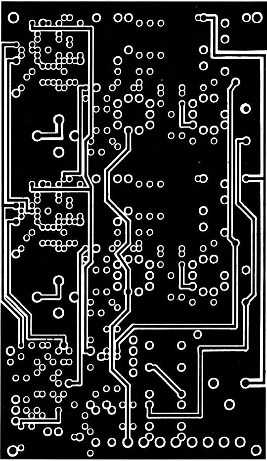
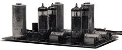
FIGURE 3
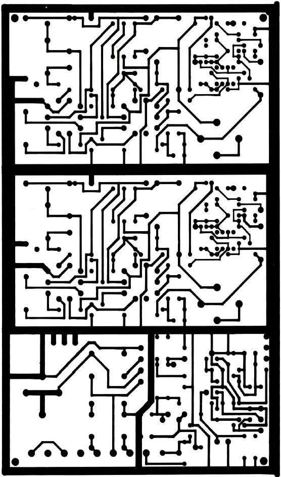
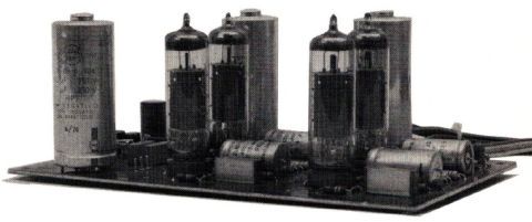
FIGURE 4
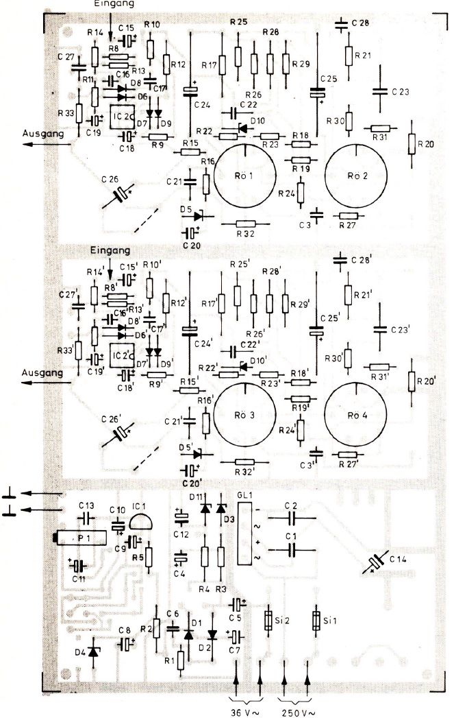
FIGURE 5: Stuffing guide.
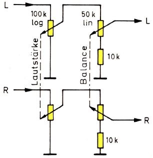
FIGURE 6: Circuit for volume and balance-input.
PART LIST
Tubes & Semiconductors
1,1', 2,2' PCL805
IC1 78L12
IC2, 2' LF351
GL1 250V, 1A bridge (B250C1000)
D1, 2 1N001
D3 ZF18 zener
D4 ZF22 zener
D5, 5' ZF8.2 zener
D6-9, 6'-9' 1N4148
D10, 10' ZF39
D11 ZF6.2 zener
Resistors
R1, 10, 10', 24, 24', 27, 27' 10Ω
R2, 25, 25', 26, 26', 28, 28', 29, 29' 1kΩ, ½W
R3 47kΩ
R4, 32, 32' 2.7kΩ, ½W
R5 100Ω
R8, 8', 11, 11', 15, 15', 16, 16', 18, 18', 23, 23' 30, 30' 1.2kΩ
R9, 9', 14, 14' 47Ω
R12, 12' 47kΩ, ½W
R13, 13' 100kΩ
R17, 17' 39kΩ, ½W
R19, 19', 22, 22', 31, 31' 1MΩ
R20, 20' 100kΩ, ½W
R21, 21' 22kΩ, ½W
R33, 33' 100Ω, ½W
P1 10kΩ trimmer
All resistors are ¼W, ±5% metal film unless indicated otherwise.
Capacitors
C1, 2 .047µF, 630V
C3, 3' .001µF, 250V
C4, 11, 12 100µF, 24V electrolytic
C5, 7 47µF, 50V electrolytic
C6, 13 .047µF, 50V ceramic
C8 220µF, 25V electrolytic
C9, 10 1µF, 35V tantalum
C14 220µF, 350V electrolytic
C15, 15', 18, 18', 19, 19', 20, 20' 10µF, 25V tantalum
C16, 16' 21, 21' 100pF ceramic
C17, 17' 10pF ceramic
C22, 22' .22µF, 100V
C23, 23' .22µF, 250V
C24, 24', 25, 25' 10µF, 350V electrolytic
C26, 26' 220µF, 250V electrolytic
C27, 27' 330pF ceramic
C28, 28' .001, 350V ceramic
Hardware
Si1 (Fuse 1) 0.1A slow blow
Si2 (Fuse 2) 0.8A slow blow
Transformer
Primary 118V AC
Secondary 1 250V, 100mA
Secondary 2 36V @ 700mA
Four 9-pin tube sockets, 2 to 8-pin dual in-line IC sockets.
Optional Controls
Volume: Dual 100kΩ log potentiometer
Balance: Dual 50kΩ linear potentiometer
(2) 10kΩ ½W fixed resistors
TABLE I
MEASUREMENT RESULTS OF THE FINAL PRODUCT
Output Power 3.4W into 100Ω
RMS at 1kHz/1% THD 6.6W into 600Ω
THD 1kHz/100mW 0.007% into 100Ω
THD 1kHz/100mW 0.004% into 600Ω
Intermodulation 600/6000Hz, 4:1 0.005% into 600Ω
Power bandwidth - 3dB 2Hz-120kHz into 100Ω
Power bandwidth - 3dB 1Kz-140kHz into 600Ω
Dumping factor >104
Input sensitivity 0.2V for 1W into 100Ω
Input sensitivity 0.5V for 1W into 600Ω
Input impedance 100kΩ (without volume control)
Signal-to-noise ratio 113dB(A), 50mW into 600Ω
Signal-to-noise ratio 138dB(A), 2W into 600Ω
Output voltage 80V RMS
Slew rate (40V into 600Ω) 80V/µSec
Power output 2-3 dynamic phones (impedance approx. 400Ω)
Power supply 220V/50Hz, 40VA
")
")
")
")
")