David Hafler
Modernize your Williamson Amplifier
Audiocraft, Volume I, Number 3, January 1956
The Williamson amplifier circuit was first publicized in England in 1947, and in this country in 1949. It has achieved wide acceptance and popularity, and has been the basis for several modifications of the original design. The most basic change was the ultra-linear version of operation, which I developed and subsequently described*. This arrangement corrected 2 of the basic defficiencies in the original design - it increases the power capability of the amplifier to 25 or 30 watts, and it improved the margin of feedback stability.
Now, as always happens, progress in amplifier design has continued: it is possible to make further improvements in the Williamson design (both triode and ultralinear versions). These improvements again correct for limitations with respect to power output and stability.
Increasing Power Output
Present thinking on requirements for audio power is vastly different from that of a few years ago. Then, most people said, "Ten watts is enough for me". Now, however, modern program material has been increased the power requirements substantially for realistic, undistorted reproduction. In addition, source material frequency responce has been extended, and this also introduces the need for re-evaluation of amplifier power requirements. Increased frequency response means that the amplifier has to handle power at greater extremes of frequency. At these extremes, the impedance characteristics of the loudspeaker change from the nominal values. This means that the amplifier is mismatched at frequency extremes, and a mismatch decreases the maximum-power capabilities of any amplifier.
To deliver clean power into a loudspeaker load, an amplifier must be capable of at least twice the power required for a resistor load such as used in measuring and rating amplifiers. Thus the extension of both dynamic range and frequency range in modern recordings, FM sources, and tape means that 25 watts are about a minimum if top-grade performance is required. Even this minimum will probably be increased in the years to come unless the efficiency of loudspeaker systems can be increased.
For these and related reasons, efforts have been devoted to increasing the power output of audio amplifiers. The advent of some new tube types has made this practical within the Williamson configuration without the need for completely rebuilding the amplifier. Changes required are replacement of the output tubes, substitution of an output transformer which will handle the increased power and provide suitable impedance matching, and addition of fixed bias.
New Output Tubes
The new tube selected for modernization of the Williamson is the Amperex 6CA7, which is also imported and distributed as the Mullard EL-34. This is a compact tube with power capabilities up to 100 watts, depending on the supply voltages available. It can be plugged directly into the sockets formerly used for 5881's, KT66's, 1614's, and other tubes of this type, with the single additional requirement that the No. 1 pins must be grounded.
The 6CA7/EL-34 is a pentode tube of extreme linearity. Its preferred operating condition is as pentode: although the manufacturer furnishes triode ratings for the tube, triode operation results in higher distortion and reduced power output. The conventional ultra-linear connection cannot provide optimum results with these tubes either, since there is no type of operation more linear than the pentode connection for which they were designed. As will be discussed later, however, a compromise form of operation fits the needs of the Williamson modernization very nicely.
To derive the potential benefits available in these tubes, proper impedance matching must be obtained in the output transformer. The Dynaco A-430 transformer has been designed specifically for this purpose. This is a 50-watt unit, the performance of which exceeds Mr. Williamson's specifications with respect to frequency response, permissible feedback, power handling ability, and so on. At present this is the only commercial transformer of correct impedance, but it is anticipated that others may be available soon.
The Dynaco A-430 has primary taps which can be used to furnish about 10% screen loading. This does not cause deterioration of the extreme linearity of the tubes, and it does have the advantage of lowering the internal impedance (for better damping). Further, it improves the inherent regulation of the output stage to the point where no changes need be made in the B+ supply of the basic Williamson in order to use the new tubes.
This transformer can be interchanged directly with units formarly used in this circuit. If the original output tubes were triode connected, the 100-ohm screen suppressors connected from pin 3 to pin 4 should be removed, and the transformer leads connected as indicated in schematic diagram (Fig. 1).
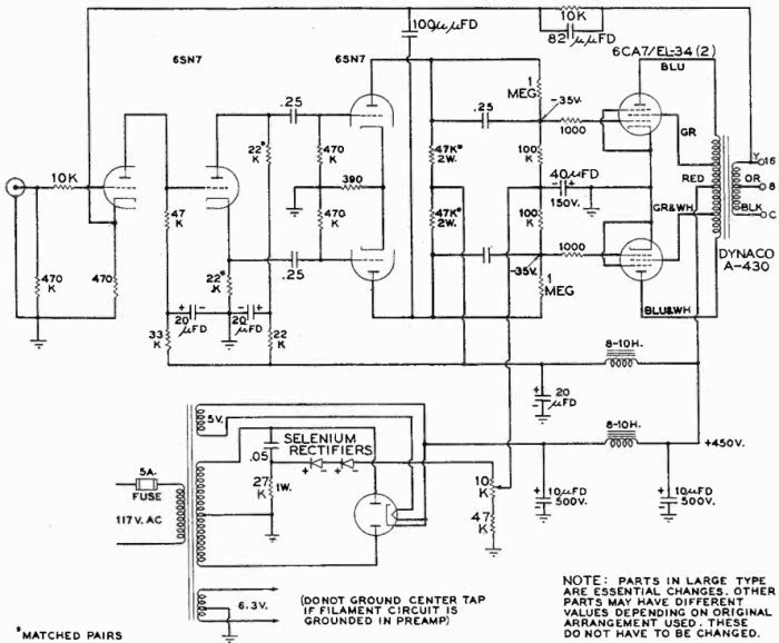
Fig. 1. Complete circuit diagram of a Williamson amplifier modified as described.
The constructor should note that the circuit must be traced from the phase inverter to the output grids in order to determine which of the output tubes is the "top" one in the circuit. Transformer leads must be properly connected to the output tubes, or the feedback phasing will be incorrect. If there is a loud buzz after connecting the transformer, the plate and screen lead from one output tube should be transferred to the other, and vice versa.
Figs. 2 and 3 show the A-430 mounted on a converted Heathkit W-3M (See Appendix for specific conversion instructions regarding this amplifier). It fits the space, despite its large size, because it has no flanges. Installation of the transformer requires no mechanical alterations in the chassis except, possibly, reaming the mounting holes to accommodate mounting studs.
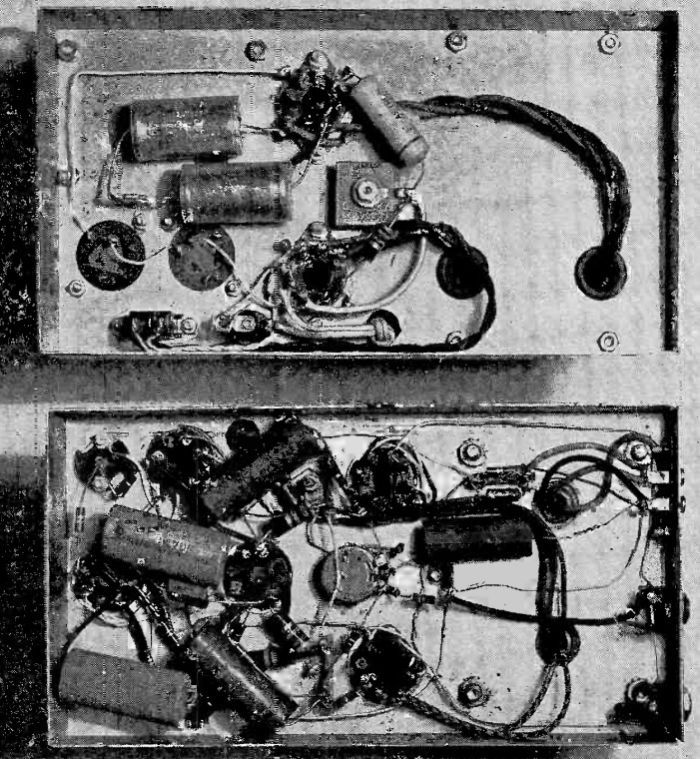
Fig. 2. Heathkit amplifier converted to deliver 50 watts with greater stability.
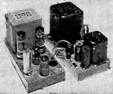
Fig. 3. New transformer goes on easily.
Biasing the Output Tubes
The 6CA7/EL-34 requires a lower value of bias than tubes generally used in Williamson amplifiers. Value of the cathode resistor should be reduced to about 200 ohms from the conventional 250 to 300 ohms. When this has been done, after substituting tubes and output transformer, the resulting amplifier can put out 35 to 40 exceptionally clean watts. However, the capabilities of the new tubes and transformer are not fully exploited unless the constructor is willing to incorporate a fixed-bias supply to replace the original self-biasing arrangement.
Addition of a negative DC supply for fixed bias is quite simple. A capacitor of .05μfd is taken from one side of the high-voltage secondary of the power transformer and connected in series with a 27,000-ohm, 1-watt resistor to ground. These form a dividing network which cuts the AC voltage from the power transformer to less than 1/3 its full value. Two small selenium rectifiers (20 ma or higher rating) are wired in series from this junction, with the negative rectifier terminals toward the output side. The resulting negatice DC is filtered by a 10,000-ohm potentiometer and a 47,000-ohm fixed resistor, and the arm of the pot is bypassed by a 40-μfd (or greater), 150-volt capacitor. This is shown in the diagram, Fig. 1. The potentiometer can be placed conveniently in the hole that formerly held the bias-balancing pot. A bias-balance adjustment is no longer required, since the output transformer is of a design in which performance is not deteriorated by moderate current unblance, and the tubes used do not have much variation in plate current drain.
The new potentiometer controls the bias voltage, which is fed to the bottom ends of the two 100,000-ohm output-tube grid resistors. These, of course, are no longer connected to the components formerly used in bias balancing.
The combination of changes described above has increased the power of the amplifier to about twice its ultra-linear rating and about 4 times its triode rating. This change alone makes an important improvement, but an equally important improvement can also be made by extending the stability margin of the amplifier.
Stabilizing the Amplifier
Criteria for good amplifier design have changed in recent years, and the stress is now being placed more and more on amplifier stability. Many amplifiers, while performing well under steady-state conditions, have exhibited muddy and harsh qualities when reproducing music. One reason for this is the fact that their transient performance is inferior to that under steady-state conditions. Another reason is that amplifier performance on loudspeaker loads id often not as good as it is with resistor loads. This point was touched on briefly before: its ramifications with respect to feedback instability are far-reaching. Many designers have come to the conclusion that stability has more effect on listening quality than distortion does! Consequently, increases in the margin of stabillity are important problems.
By these standards, then, original Williamson amplifiers have inadequate stability at both extreme low and high frequencies. This can be demonstrated for the low end by touching the input grid momentarily with the fingertip and watching the speaker cone. The heavy low-frequency transient which is generated triggers the amplifier, and there are usually several surgees before the effect is damped out. The speaker cone can be observed to move back and forth several times before coming to rest. This means that short signal impulses will also cause spurious cone movements which tend to blur the sound.
At high frequencies, the corresponding effect can be ciewed on an oscilloscope with a square-wave signal input. A rippled square wave is indicative of basic instability, and indicates that there is a transient distortion of high-frequency signals.
Instability is due to the fact that the phase characteristics of the amplifier cause some of the feedback to be applied positevely instead of negatively at the frequency extremes. The remedy is superficially simple - to shift the phase in the right direction at the critical frequencies. It is not always simple to do this. Fortunately, the phase characteristics of the A-430 transformer and the Williamson circuit arrangement permit complete correction of the low frequency phase characteristic and appreciable correction of the high-frequency characteristic. These corrections are made with a few inexpensive components.
The low-frequency correction is achieved by shunting the 0.25-μfd coupling capacitors which go to the output grids with 1 megohm resistors. High-frequency correction is obtained with a 100-μμfd capacitor which is connected from the lower driver plate to the cathode of the first stage. Without going into the theory underlying these corrections, it is worth mentioning that they have a tremendous effect on performance. (It is assumed that the 10,000-ohm resistor in the input grid, change of the .05-μfd capacitors to 0.25, and the use of a small capacitor across the feedback resistor as indicated in the schematic are already included in the amplifier. If not, these should also be added in accordance with previous recommendations*).
This completes the modernization of the Wiiliamson. If the power supply puts out a full 450 volts with reasonable regulation, the output power will be about 50 watts at 1% IM distortion. If the power supply provides lower voltage, the output power will be reduced somewhat. Below full output, the distortion drops rapidly toward a vanishing point. The frequency response of the amplifier will be approximately the same as that of the original version except that peaks in the response (associated with instability) are eliminated. The transient response - that unmeasurable intangible - will be audibly better. It will be particularly evident in more solid, better-defined bass and smoother, cleaner treble.
Appendix
The following specific hints will be helpful to those who are interested in modernizing the Heathkit W-3M Williamson:
The bias voltage divider and rectifier can go in the power supply chassis. Output of the selenium rectifier is connected to pin 5 of the power socket and carried through the spare wire in the connecting cable to one side of the 10,000-ohm bias-setting pot.
The 250-ohm and two 100-ohm resistors are discarded, as is the 100-ohm pot. The bias pot replaces the 100-ohm balance adjustment, and the blank tie points to which the 100-ohm resistors were fastened can then be used to connect leads which are part of the ground circuit.
In the interests of economy, the 20-μfd capacitor which formerly bypassed the cathodes can be used for filtering the bias supply. The schematic calls for 40-μfd, but the difference in hum level is only 2 dB.
Jacks formerly used for metering plate current can still be used to check equality of the output tubes. The former connection to the 250-ohm bias resistor must now be grounded in order to complete the circuit path for the cathode current. At the same time the No. 1 pins (suppressor grids of the output tubes) should be connected at the socket to the No. 8 (cathode) pins.
In order to insert the 10,000-ohm parasitic suppressor resistor directly at the input grid, the 2.2-megohm resistor should be reconnected directly from the input socket to ground. The 10,000-ohm resistor can then be inserted from the input connector to pin 1 of the first 6SN7 tube. This replaces the .05-μfd capacitor which is used as part of the bias supply in the power chassis. Make sure that the preamplifier used has an output coupling capacitor since the amplifier now has none in the input. Practically all preamplifiers are so equipped; if not, one should be added.
The .05-μfd coupling capacitors between the two 6SN7's should be increased to 0.25-μfd. Care should be exercised in order to get these to fit the space. If difficulty is encountered, it is suggested that miniature capacitors be used, such as Aerolites made by Aerovox.
The 1-megohm phase-correcting resistors across the coupling capacitors permit some positive DC to appear on the grids if the negative bias supply is inoperative. The existence of negative voltage at the grid should be checked with the rectifier removed before permitting the B+ voltage to be applied. Then the rectifier should be inserted and the bias set to 35 volts from grid to ground after the tubes have had time to warm up. Do not remove the second 6SN7 while the amplifier is on, because this will cause additional positive voltage to be applied to the grids of the output stage, upsetting the bias and possibly harming the tubes.
Audiocraft Test Results
The amplifier shown in Figs. 2 and 3, which was the basic Williamson converted in accordance with this article, produced 0.6% IM distortion at 50 watts output, 0.2% at 36 watts, and 0.1% at 15 watts. Below 12 watts distortion was in the residual range of the meter and could reasonably be called negligible if not unmeasurable. Test frequencies were 60 and 7,000 cps mixed in a 4-to-1 ratio.
These readings could have been improved slightly by using parts matched more precisely, or by adding to the power supply filtering. It id doubtful that such small improvements wpuld be apparent audibly. On the other hand, if the phase inverter balance were off, or certain other elements had drifted in value, the distortion figures might be doubled - still exceptionallt good performance.
Frequency response was perfectly flat within the range of our test equipment. Calculated response, without the 100-μμfd feedback capacitor at the driver stage plate, is ±1 db from 2 to 200,000 cps; with this added response above 80,000 cps slopes off smoothly. This capacitor causes a very slight increase in distortion at 20,000 cps, which is quite insignificant compared to the 12 db increase in the high-frequency stability margin. Stability at the low end, determined by recovery characteristics from a sharp overload pulse, was apparently perfect.
Square-wave response at low-frequencies was excellent, and exceptionally good at high frequencies. Power response was completely flat from 20 to 20,000 cps at 50 watts. Total cost for all parts required to make the complete convertion: less than $40.00.
* Hafler, D., and Keroes, H. I., "Improving the Williamson Amplifier", Radio & Television News, February 1953.
The material was provided by Grzegorz Makarewicz, 'gsmok'
")
")
")
")
")